Made with
UML Class Diagram Example - Social Networking Site
This sample was created in ConceptDraw DIAGRAM diagramming and vector drawing software using the UML Class Diagram library of the Rapid UML Solution from the Software Development area of ConceptDraw Solution Park.
This sample shows the structure of the popular social networking site Linkedin and is used in the business field, in IT, at the projection and creating of the social networking sites.
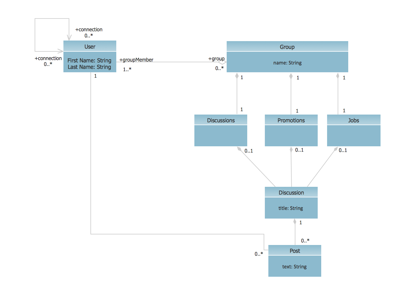
Example 1. UML of the Social Networking Site (Linkedin)
Using the libraries of the Rapid UML Solution for ConceptDraw DIAGRAM you can create your own visual vector UML diagrams quick and easy.
UML Resource:
- UML Software
- How to create a UML Diagram
- UML Diagram Examples
- Class Diagram
- Use Case Diagram
- Timing Diagram
- Interaction Overview Diagram
- Communication Diagram
- State Machine Diagram
- Activity Diagram
- Deployment Diagram
- Package Diagram
- Collaboration Diagram
- Object Diagram
- Sequence Diagram
- Composite Structure
- Component Diagram
TEN RELATED HOW TO's:
How to draw Metro Map style infographics? (New York) →
How to draw Metro Map style infographics of New York subway. New York Subway has a long history starting on October 27, 1904. Since the opening many agencies have provided schemes of the subway system. At present time are 34 lines in use. This page present New York City subway map construct with Metro Map Solution in Conceptdraw DIAGRAM software. This is a one-click tool to add stations to the map. It lets you control the direction in which you create new stations, change lengths, and add text labels and icons. It contains Lines, Stations, and Landmarks objects 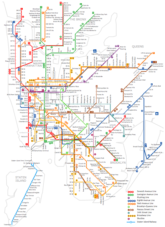
Picture: How to draw Metro Map style infographics? (New York)
Related Solution:
UML for Bank →
UML for Bank - This sample was created in ConceptDraw DIAGRAM diagramming and vector drawing software using the UML Class Diagram library of the Rapid UML Solution from the Software Development area of ConceptDraw Solution Park. 
Picture: UML for Bank
Related Solution:
Building Drawing Software for Designing Plumbing →
Any building project must respond to some requirements. Moreover, finding a drawing software for developing a waste water plan is significant. Designing plumbing plans may be difficult in the beginning, but practice makes perfect. Layout of plumbing fixtures and, kitchen equipment a is a very important part of the home's interior design. If you do not want to find out suddenly the bath in your kitchen, or stove in your bathroom, you need to pay due attention to this plan. ConceptDraw Building Plans libraries give you a number of vector objects. Using them you can quickly and professionally sketch a plan of kitchen or bathroom in proper scale and with objects depicting your desired equipment. Then your contractor never will confuse a bath with a stove and a washing machine with a toilet and your house will be really a home of your dreams. 
Picture: Building Drawing Software for Designing Plumbing
Related Solution:
UML Diagram Visio →
This sample shows the UML Class Diagram that was created in ConceptDraw DIAGRAM on the Mac and then was opened for editing in MS Visio. Using the 13 libraries of the Rapid UML Solution for ConceptDraw DIAGRAM you can create your own visual vector UML diagrams quick and easy. 
Picture: UML Diagram Visio
Related Solution:
UML Package Diagram. Design Elements →
UML Package Diagram illustrates the functionality of a software system. ConceptDraw has 393 vector stencils in the 13 libraries that helps you to start using software for designing your own UML Diagrams. You can use the appropriate stencils of UML notation from UML Package library. 
Picture: UML Package Diagram. Design Elements
Related Solution:
Entity Relationship Diagram Symbols →
When we start to speak about databases, we must always mention database structure visualization. One of the most common ways to do it is to create an entity relationship diagram, and to put appropriate symbols on it. It is important either for database projecting and for its' future maintenance. Entity Relationship Diagram describes data elements and their relationships within a database. There are a set of special symbols that depict each element of an entity relationship diagram. Entities - represents some stable components such as supplier, employee, invoice, client, etc. Relation symbols show how the entities interact. Attributes define characteristics of the relationships. Attributes can be one-to-one or many-to-many. Physical symbols is used in the physical models. They represent items such as fields, tables, types and keys. ERD physical symbols are the building material for the database. Notation lines are used to illustrate the relationships. The most common method is Crow's Feet notation. You can use ConceptDraw Entity-Relationship Diagram (ERD) solution to represent a database using the Entity-Relationship model. 
Picture: Entity Relationship Diagram Symbols
Related Solution:
Metropolitan area networks (MAN). Computer and Network Examples →
A list of parameters on which networks differ is very long. A large network with a range up to 50 kilometers is called metropolitan area network (MAN), and this type of network can include several local area networks. Metropolitan networks in their turn connect into global area networks. Here you will see a Metropolitan Area Network (MAN). This is an extensive network which occupies a large territory including a few buildings or even the whole city. The space of the MAN is bigger than LAN, but lower than WAN. MAN comprise a lot of communication equipment and delivers the Internet connection to the LANs in the city area. Computer and Networks solution for ConceptDraw DIAGRAM provides a set of libraries with ready-to-use vector objects to design various kinds of computer networks. 
Picture: Metropolitan area networks (MAN). Computer and Network Examples
Related Solution:
Source: https://www.conceptdraw.com/How-To-Guide/uml-class-diagram-example-social-networking-site
Posted by: appelgateterrysays.blogspot.com
